Here’s another tutorial for those looking to save some money by adjusting their own valves.
Notice: This valve adjustment procedure was performed on a 2002 Suzuki Volusia with naked jugs (i.e. de-paired and de-filtered). Having a pair valve and/or air cleaner installed will require the removal of additional parts.
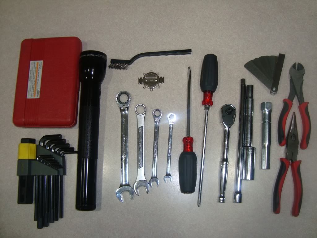
For this procedure, we need the following tools:
17mm, 10mm and a 8mm ratcheting box wrench (5/8” box wrench for Mustang seat)
3/8” socket wrench, 10mm socket, 12” extension
Phillips and slot screwdriver (size 2)
Suzuki spark plug socket (from toolkit)
Set of metric Allen wrenches
Needle nose pliers
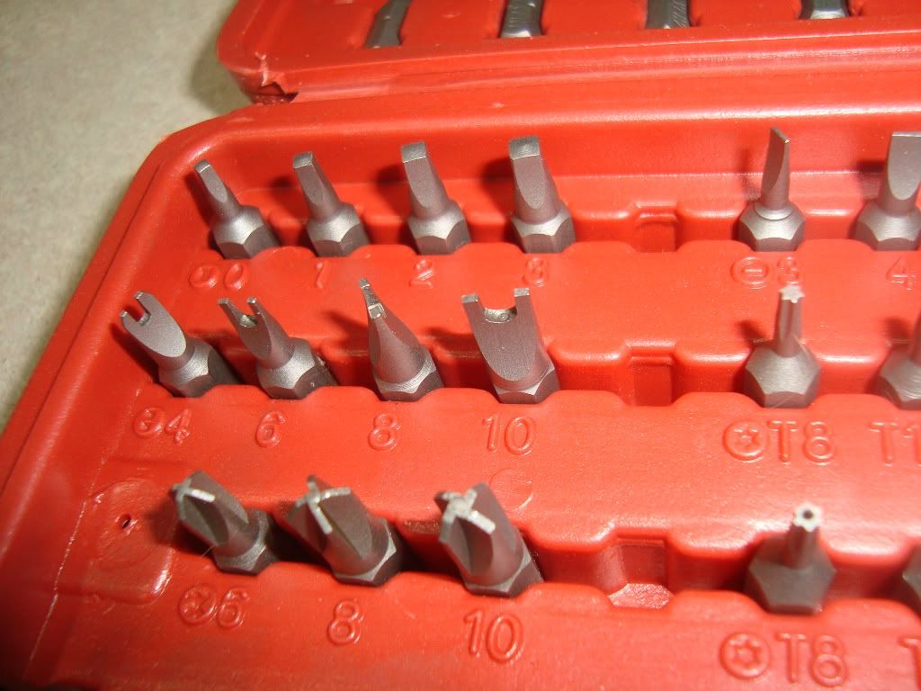
Set of security bits from Harbor Freight (will explain later)
Feeler gauges (optional)
Spark plug gap tool (for gapping spark plugs)
Wire brush (for cleaning spark plugs)
![Image]()
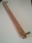
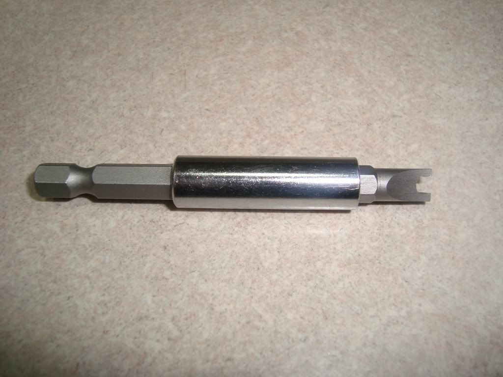
The #10 security bit from this Harbor Freight set comes in handy for holding the valve adjustment screw in place.
![Image]()
![Image]()
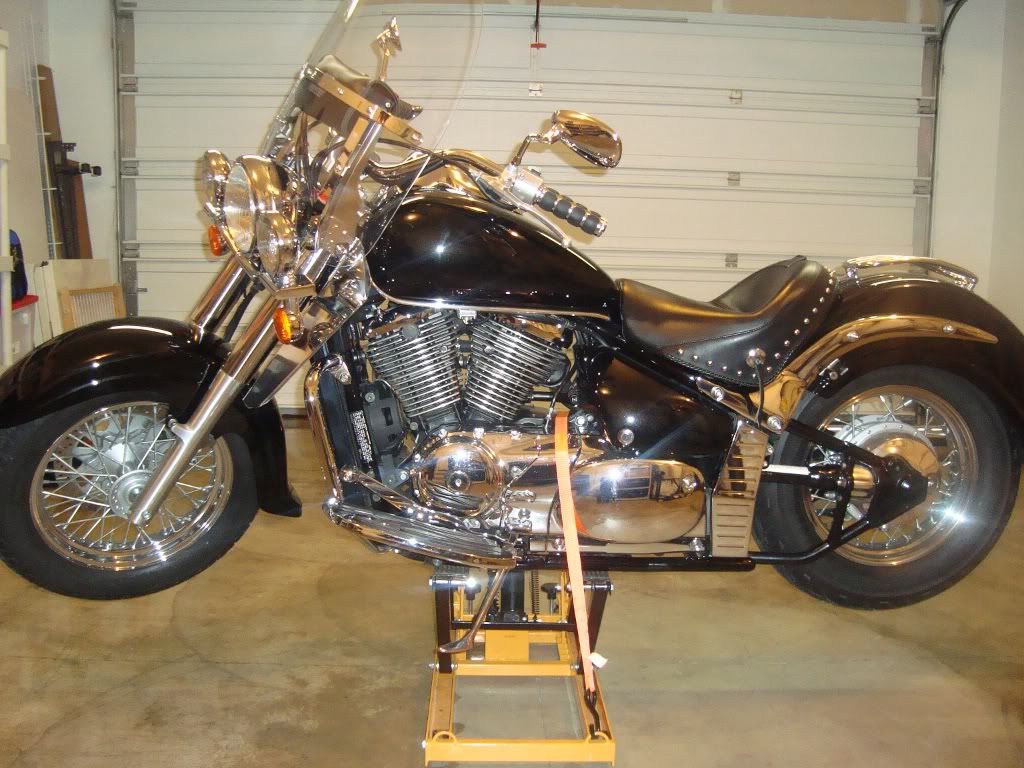
The motorcycle must be completely cold before you can accurately adjust the valves (wait 24 hours after ridding it). Secure the motorcycle to a stand or jack at a comfortable working height.
![Image]()
Remove the seat using a 6mm Allen wrench. Mustang seats require a 5/8” box wrench. Use a 3/8" socket wrench and a 12mm socket to remove the bolt holding the gast tank to the frame.
![Image]()
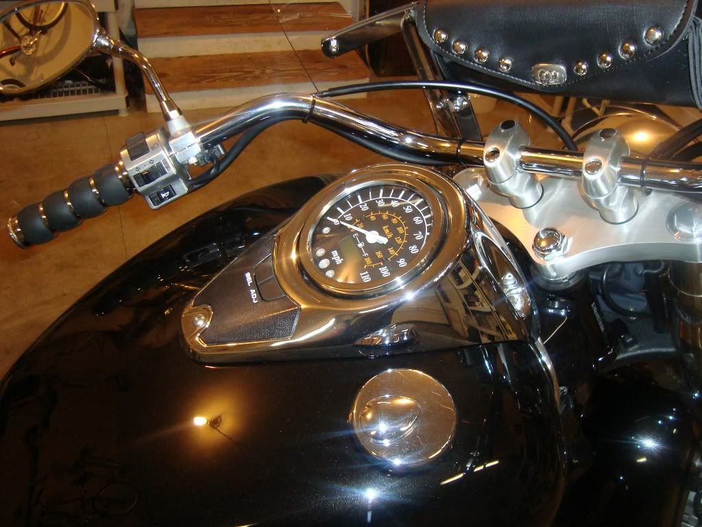
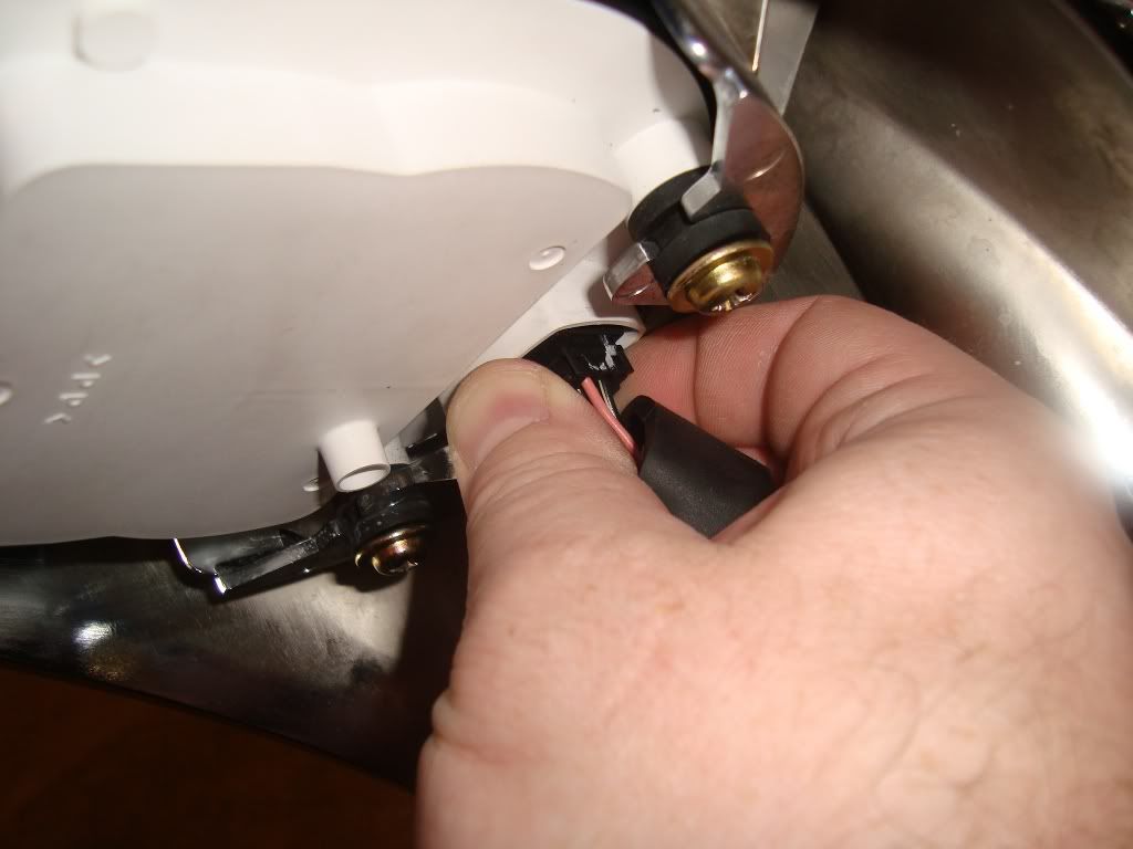
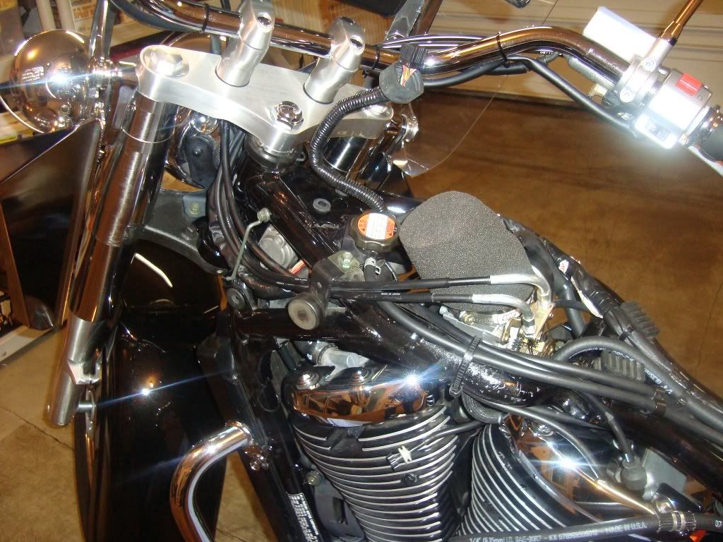
Using a 3mm and 4mm Allen wrench, detach the speedometer housing from the gas tank. Slip back the boot on the wire harness underneath and squeeze the plug so it releases from the speedometer assembly.
![Image]()
![Image]()
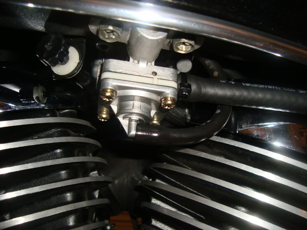
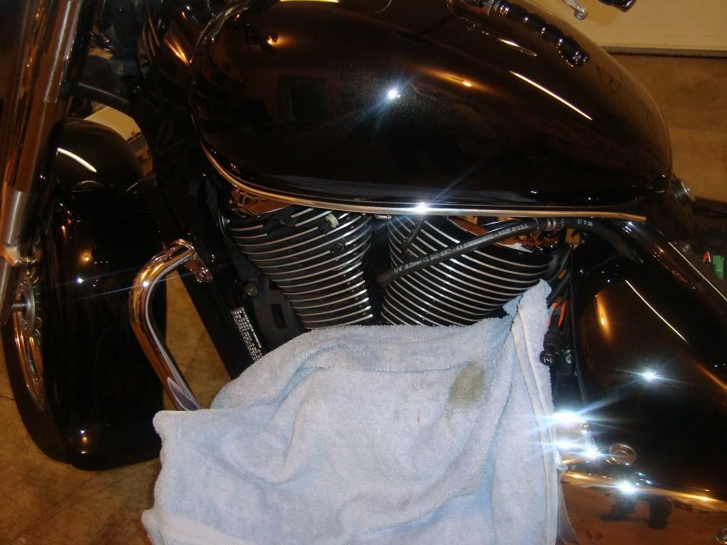
Detach the vacuum hose, fuel line and idle adjustment from the left side of the gas tank using the needle nose pliers; position an old towel to catch the fuel from the hose.
![Image]()
![Image]()
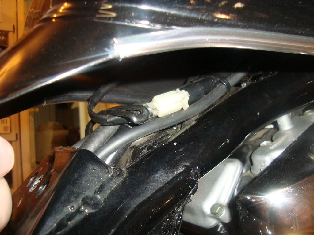
With the handlebars straight, carefully lift up the back of the tank (near the seat) and disconnect the fuel gauge sensor plug. Then, carefully remove the fuel tank from the frame. Sit the fuel tank aside on a soft surface to prevent damage to the underside.
![Image]()
Remove the plastic neck covers from both sides to expose additional working area around the valves.
![Image]()
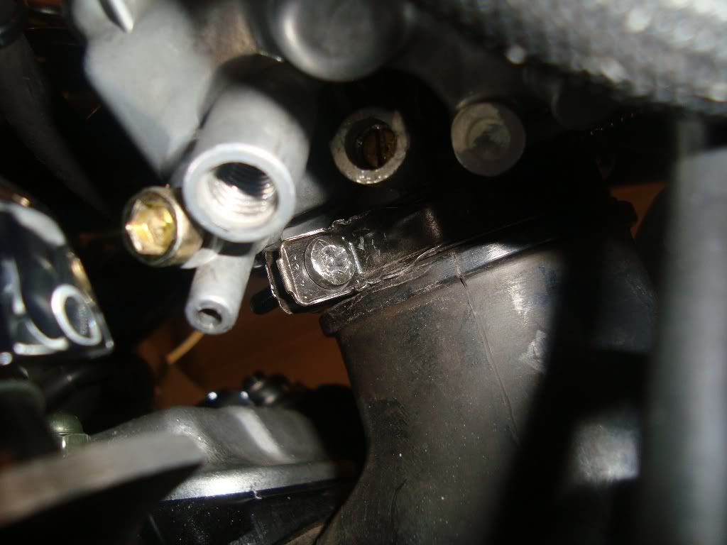
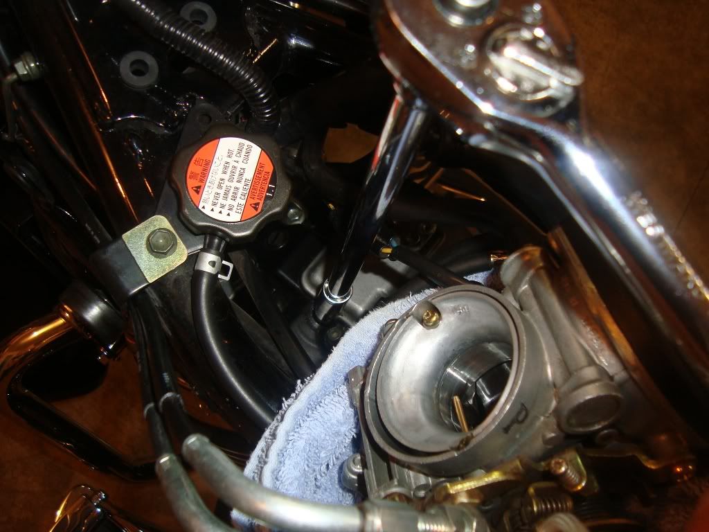
Loosen the hose clamp securing the carburetor to the intake using a Phillips screwdriver. Carefully lift up the carburetor off while rocking it back and forth. Put a towel under the carburetor to catch any excess fuel.
![Image]()
![Image]()
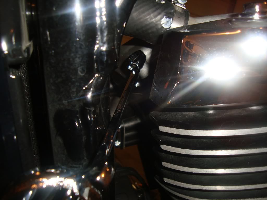
Using an 8mm ratcheting box wrench, remove the chrome sparkplug covers from both sides of the bike. Then, use the Suzuki spark plug socket and a 17mm ratcheting wrench to remove the spark plugs from the engine.
![Image]()
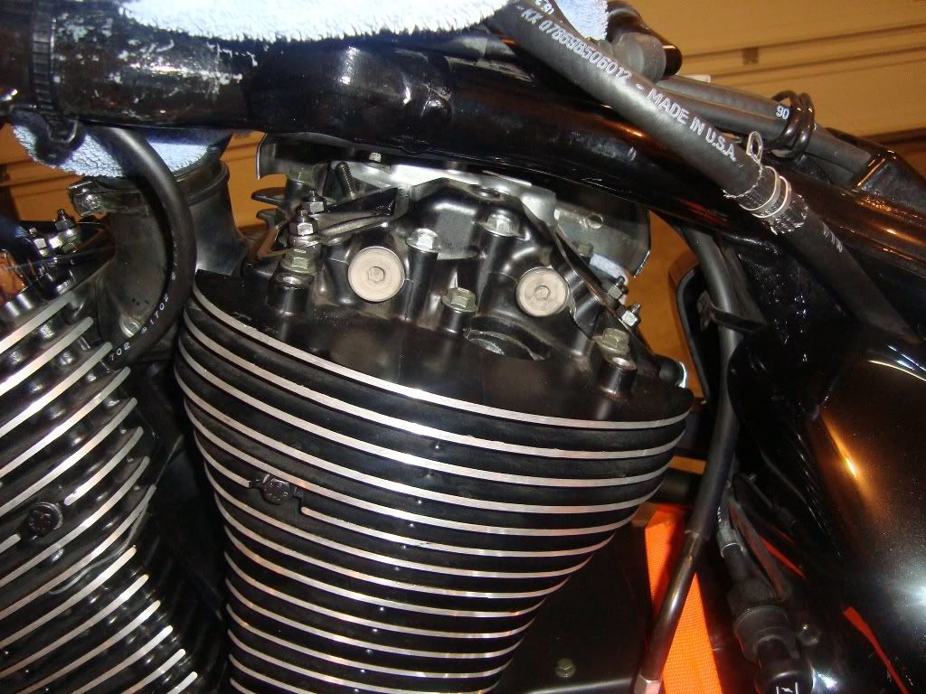
You are ready to remove the valve covers. I usually start with the harder to reach bolts because they are prone to falling. Using an 8mm ratcheting box wrench, slowly remove the hard to reach bolts on the rear right and front left covers.
![Image]()
![Image]()
Remove the 10mm nuts from the top of the bike using a 3/8” socket wrench, 10mm socket and 12” extension.
![Image]()
Remove the remaining bolts using a 8mm ratcheting box wrench. Be careful not to drop the bolts into hard to reach places.
![Image]()
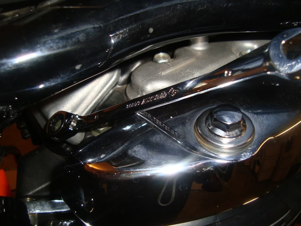
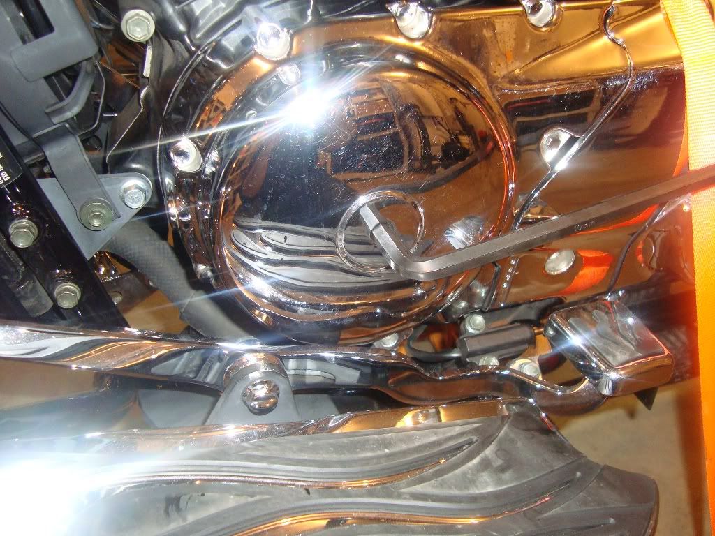
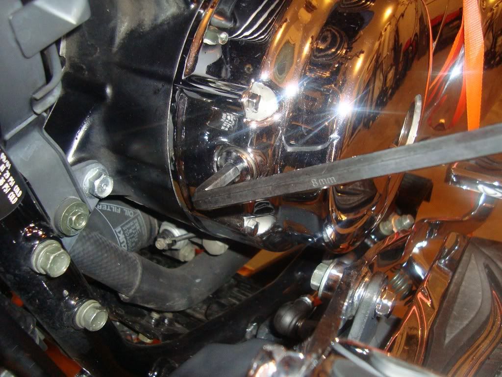
Using a 10mm and 8mm Allen wrench, remove the caps from the engine covers. The large cover is where we will be rotating the engine with a socket wrench; the small cover is a viewing hole to align the RT/FT marks (more on this later).
![Image]()
![Image]()
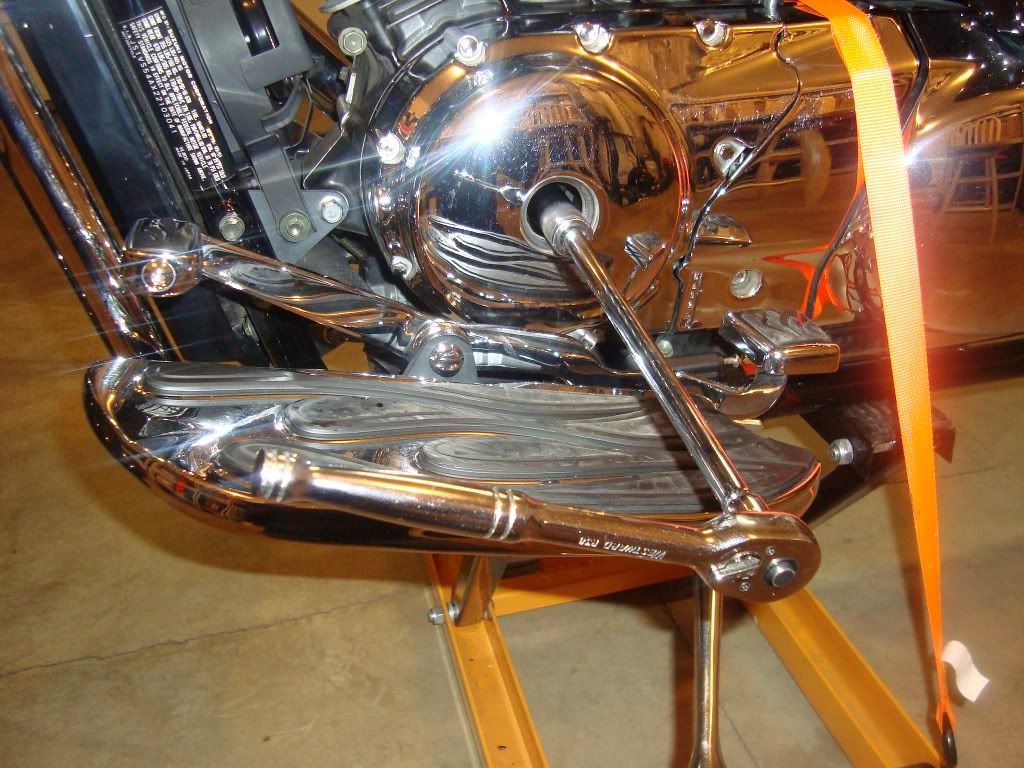
Using a 3/8” socket wrench, 17mm socket and 12” extension, slowly rotate the engine counter clockwise. The valves will begin to move up and down on both cylinders. Be aware, you should NEVER rotate the engine clockwise as it may cause damage to the engine!
![Image]()
While slowly rotating the engine, use a flashlight to look into the viewing hole. Every full rotation of the engine, you will see an R/T and F/T mark pass by. These marks help you locate the adjustment positions for either the Front (F/T) or Rear (R/T) cylinders. These positions are also called Top Dead Center (TDC).
![Image]()
Continue rotating the engine. Take notice to the valves on top of the rear cylinder. They will open and close in the following pattern:
Exhaust – open (down)
Exhaust – close (up)
Intake – open (down)
Intake – close (up)
Here’s a video showing the above pattern:
http://s1225.photobucket.com/albums....com/albums/ee393/OregonLAN/Volusia Riders/?action=view¤t=valve_video.mp4
As soon as the intake valves on the rear cylinder close (as shown at the end of the video), use a flashlight to look for the R/T in the viewing hole. Slowly rotate the engine until the R/T mark is dead center in the viewing hole. This is the adjustment point for the rear cylinder. If you accidentally bypass the mark, you will have to rotate the engine around a couple times until the valves open and close again.
Finding the adjustment points on the front valves is done in a similar manner. Rotate the engine counter clockwise until both the exhaust and intake valves on the front cylinder have opened and closed. Use a flashlight and slowly rotate the engine until the F/T mark is dead center in the viewing hole.
Work on one cylinder at a time. Use a 10mm ratcheting box wrench to loosen the retention nuts around the valve adjustment screws. Loosen the valve adjustment screws using the #10 security bit until they can be rotated by hand.
You can adjust the valves using either a feeler gauge or the “Jpaige” method. A feeler gauge is arguably the most accurate method, but it’s also the most difficult method.
The specification for the exhaust and intake are as followed:
Exhaust - .007 - .009
Intake - .003 - .005
Insert the feeler gauge between valve adjustment screw and the lifter as shown. You will have to bend the tip of the feeler gauge to get an accurate adjustment on all the lifters.
![Image]()
![Image]()
The “Jpaige” method doesn’t require a feeler gauge. It’s based off a mathematical calculation of the screw’s thread pitch. You simply finger tighten the valve screw until it touches the valve lifter. Then, you back out the exhaust screw 1/4 turn (90 degrees) and the intake screw 1/8 turn (45 degrees).
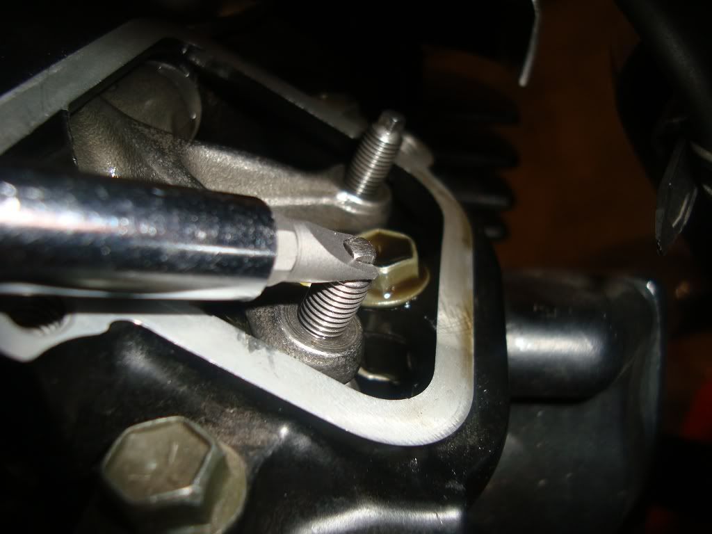
Adjust and secure each valve individually. Use the #10 security bit tool to hold the valve adjustment screw in place while you tighten the retention nut with a 10mm ratcheting box wrench.
![Image]()
Assemble your bike in reverse order. If everything is adjusted properly, you should hear a very faint ticking noise at idle (commonly associated with a sewing machine). Improperly adjusted valves will result in excessive ticking noise, poor performance and overheating.
While everything is accessible, now is a good time to clean off or replace your sparkplugs and check the gap. Use a wire brush to clean off the soot and the gapping tool to adjust them as followed:
0.8 – 0.9mm (0.031 – 0.035 in)
Notice: This valve adjustment procedure was performed on a 2002 Suzuki Volusia with naked jugs (i.e. de-paired and de-filtered). Having a pair valve and/or air cleaner installed will require the removal of additional parts.
For this procedure, we need the following tools:
17mm, 10mm and a 8mm ratcheting box wrench (5/8” box wrench for Mustang seat)
3/8” socket wrench, 10mm socket, 12” extension
Phillips and slot screwdriver (size 2)
Suzuki spark plug socket (from toolkit)
Set of metric Allen wrenches
Needle nose pliers
Set of security bits from Harbor Freight (will explain later)
Feeler gauges (optional)
Spark plug gap tool (for gapping spark plugs)
Wire brush (for cleaning spark plugs)
The #10 security bit from this Harbor Freight set comes in handy for holding the valve adjustment screw in place.
The motorcycle must be completely cold before you can accurately adjust the valves (wait 24 hours after ridding it). Secure the motorcycle to a stand or jack at a comfortable working height.
Remove the seat using a 6mm Allen wrench. Mustang seats require a 5/8” box wrench. Use a 3/8" socket wrench and a 12mm socket to remove the bolt holding the gast tank to the frame.

Using a 3mm and 4mm Allen wrench, detach the speedometer housing from the gas tank. Slip back the boot on the wire harness underneath and squeeze the plug so it releases from the speedometer assembly.
Detach the vacuum hose, fuel line and idle adjustment from the left side of the gas tank using the needle nose pliers; position an old towel to catch the fuel from the hose.
With the handlebars straight, carefully lift up the back of the tank (near the seat) and disconnect the fuel gauge sensor plug. Then, carefully remove the fuel tank from the frame. Sit the fuel tank aside on a soft surface to prevent damage to the underside.
Remove the plastic neck covers from both sides to expose additional working area around the valves.
Loosen the hose clamp securing the carburetor to the intake using a Phillips screwdriver. Carefully lift up the carburetor off while rocking it back and forth. Put a towel under the carburetor to catch any excess fuel.

Using an 8mm ratcheting box wrench, remove the chrome sparkplug covers from both sides of the bike. Then, use the Suzuki spark plug socket and a 17mm ratcheting wrench to remove the spark plugs from the engine.

You are ready to remove the valve covers. I usually start with the harder to reach bolts because they are prone to falling. Using an 8mm ratcheting box wrench, slowly remove the hard to reach bolts on the rear right and front left covers.
Remove the 10mm nuts from the top of the bike using a 3/8” socket wrench, 10mm socket and 12” extension.
Remove the remaining bolts using a 8mm ratcheting box wrench. Be careful not to drop the bolts into hard to reach places.
Using a 10mm and 8mm Allen wrench, remove the caps from the engine covers. The large cover is where we will be rotating the engine with a socket wrench; the small cover is a viewing hole to align the RT/FT marks (more on this later).
Using a 3/8” socket wrench, 17mm socket and 12” extension, slowly rotate the engine counter clockwise. The valves will begin to move up and down on both cylinders. Be aware, you should NEVER rotate the engine clockwise as it may cause damage to the engine!
While slowly rotating the engine, use a flashlight to look into the viewing hole. Every full rotation of the engine, you will see an R/T and F/T mark pass by. These marks help you locate the adjustment positions for either the Front (F/T) or Rear (R/T) cylinders. These positions are also called Top Dead Center (TDC).

Continue rotating the engine. Take notice to the valves on top of the rear cylinder. They will open and close in the following pattern:
Exhaust – open (down)
Exhaust – close (up)
Intake – open (down)
Intake – close (up)
Here’s a video showing the above pattern:
http://s1225.photobucket.com/albums....com/albums/ee393/OregonLAN/Volusia Riders/?action=view¤t=valve_video.mp4
As soon as the intake valves on the rear cylinder close (as shown at the end of the video), use a flashlight to look for the R/T in the viewing hole. Slowly rotate the engine until the R/T mark is dead center in the viewing hole. This is the adjustment point for the rear cylinder. If you accidentally bypass the mark, you will have to rotate the engine around a couple times until the valves open and close again.
Finding the adjustment points on the front valves is done in a similar manner. Rotate the engine counter clockwise until both the exhaust and intake valves on the front cylinder have opened and closed. Use a flashlight and slowly rotate the engine until the F/T mark is dead center in the viewing hole.
Work on one cylinder at a time. Use a 10mm ratcheting box wrench to loosen the retention nuts around the valve adjustment screws. Loosen the valve adjustment screws using the #10 security bit until they can be rotated by hand.
You can adjust the valves using either a feeler gauge or the “Jpaige” method. A feeler gauge is arguably the most accurate method, but it’s also the most difficult method.
The specification for the exhaust and intake are as followed:
Exhaust - .007 - .009
Intake - .003 - .005
Insert the feeler gauge between valve adjustment screw and the lifter as shown. You will have to bend the tip of the feeler gauge to get an accurate adjustment on all the lifters.


The “Jpaige” method doesn’t require a feeler gauge. It’s based off a mathematical calculation of the screw’s thread pitch. You simply finger tighten the valve screw until it touches the valve lifter. Then, you back out the exhaust screw 1/4 turn (90 degrees) and the intake screw 1/8 turn (45 degrees).
Adjust and secure each valve individually. Use the #10 security bit tool to hold the valve adjustment screw in place while you tighten the retention nut with a 10mm ratcheting box wrench.
Assemble your bike in reverse order. If everything is adjusted properly, you should hear a very faint ticking noise at idle (commonly associated with a sewing machine). Improperly adjusted valves will result in excessive ticking noise, poor performance and overheating.
While everything is accessible, now is a good time to clean off or replace your sparkplugs and check the gap. Use a wire brush to clean off the soot and the gapping tool to adjust them as followed:
0.8 – 0.9mm (0.031 – 0.035 in)
")